Initial Calibration
To ensure the highest probability of success during calibration, you should place the cameras in your desired configuration, and make sure that they are fastened tightly so that they do not subsequently move (which would invalidate the calibration). While placing the cameras, you must ensure that the camera axes are aligned as parallel as possible as demonstrated below. The factory calibration routine currently allows for a misalignment of up to 3 degrees.

When you are ready to calibrate your cameras in their new configuration, please move the sensor assembly outside. Static, daytime, natural scenes without reflective surfaces or moving objects work best. Avoid indoor, cluttered environments with artificial lighting, flat/texture-less surfaces, or bad weather conditions for this step. Ensure that the sensor assembly is stationary while performing calibration. Then simply run the Nodar Viewer app, connect it to the Hammerhead, open the Initial Calibration viewer, then open viewer’s properties, choose one or several calibration options and submit your choice, as shown below. It should be ensured that the image used for calibration is devoid of observable artifacts, like reflections and motion blur. The GUI will be disabled until the calibration is done.
Tip: press
Ctrl+Spaceto pause the stream before clickingSubmit. This ensures the frame used for calibration matches the one you see.
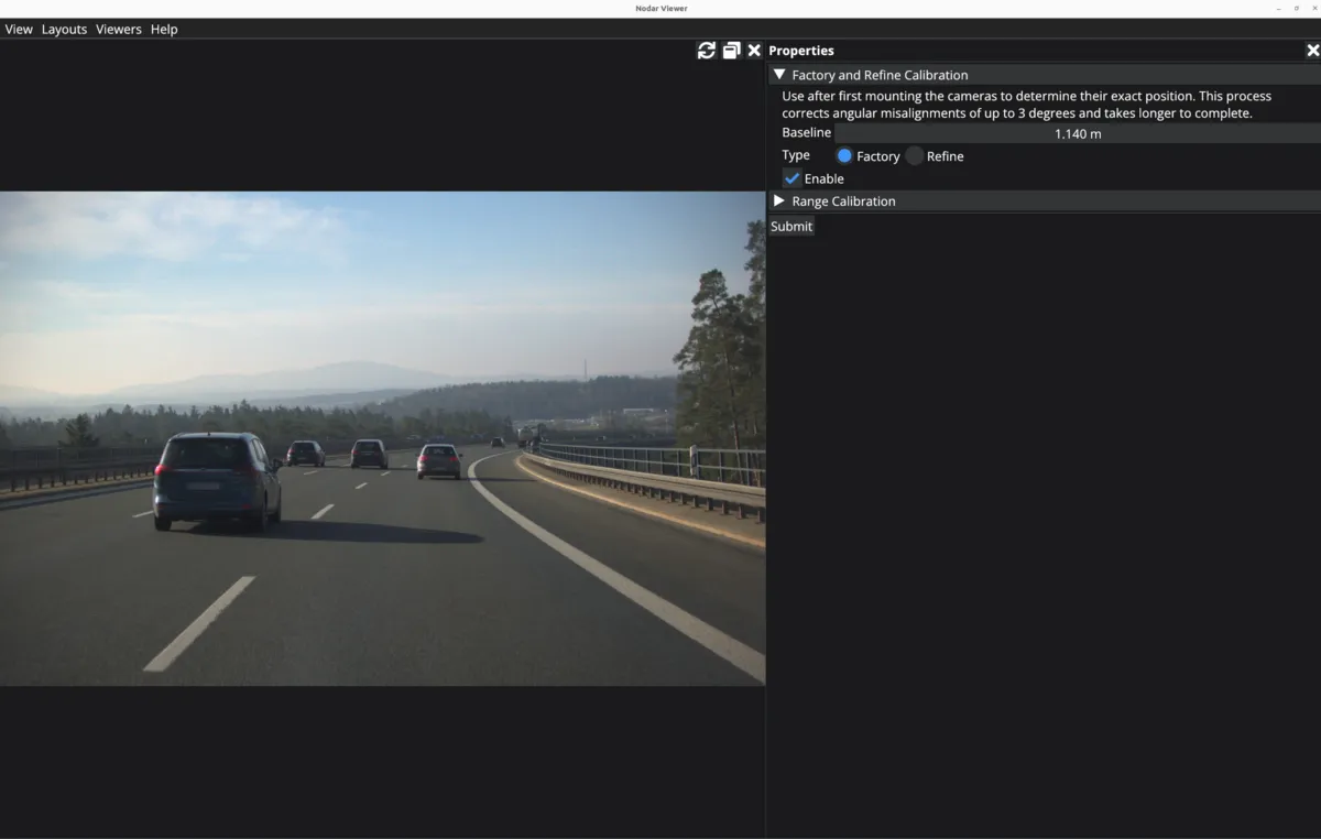
Factory Calibration
The first time that you run the calibration manager after moving the cameras from their original factory position in the enclosure, you should run the factory calibration (a long calibration routine designed to compensate for large camera axes misalignment). To use the calibration type, first enable it by clicking the Enable checkbox. Enter the baseline between the cameras (in meters). After this, the Factory option needs to be selected. Click on Submit and wait for the calibration to finish.
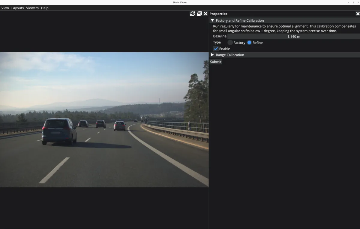
Refine Calibration
There is also an option to run a shorter, refinement calibration instead of a long factory calibration. This calibration type can be run as part of regular maintenance to maintain optimal alignment. To use the calibration type, first enable it by clicking the Enable checkbox. Enter the baseline between the cameras (in meters). After this, the Refine option needs to be selected. Click on Submit and wait for the calibration to finish.
Range Calibration
There is a third calibration option to calibrate range. This is required to be performed after any changes in the configuration of the cameras.
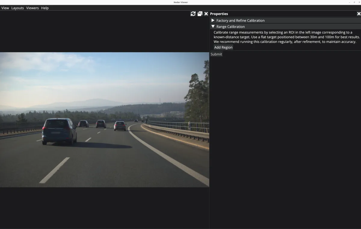
Click on Add Region which will make the viewer interactive and you can draw a rectangle. Resize the window to an appropriate size, and then select a relatively flat object near the center of the image which is sufficiently far away (>20m). This area can be selected by holding down the left mouse button and drawing on the selected object in the image. If you need to re-draw for any reason, just start to draw a new rectangle to reset your previous selection. Once you are finished selecting an appropriate area, enter the distance (in meters) to the selected object in the input field.

Optionally, you can enter multiple regions for doing the range calibration.

Press the Submit button after you are done selecting the regions. The distance should be measured accurately such as by using a Laser Distance Meter from the left camera.
Note that factory calibration only needs to be run once after the cameras are moved to a new physical configuration. Depending on your system, this process can take a few minutes to conclude. In addition, if at any point while operating the system, you notice that the disparity estimates seem sparse or range estimates are off, even with camera axes are aligned to within 3 degrees of each other, you may try rerunning the calibration refinement and range calibration.
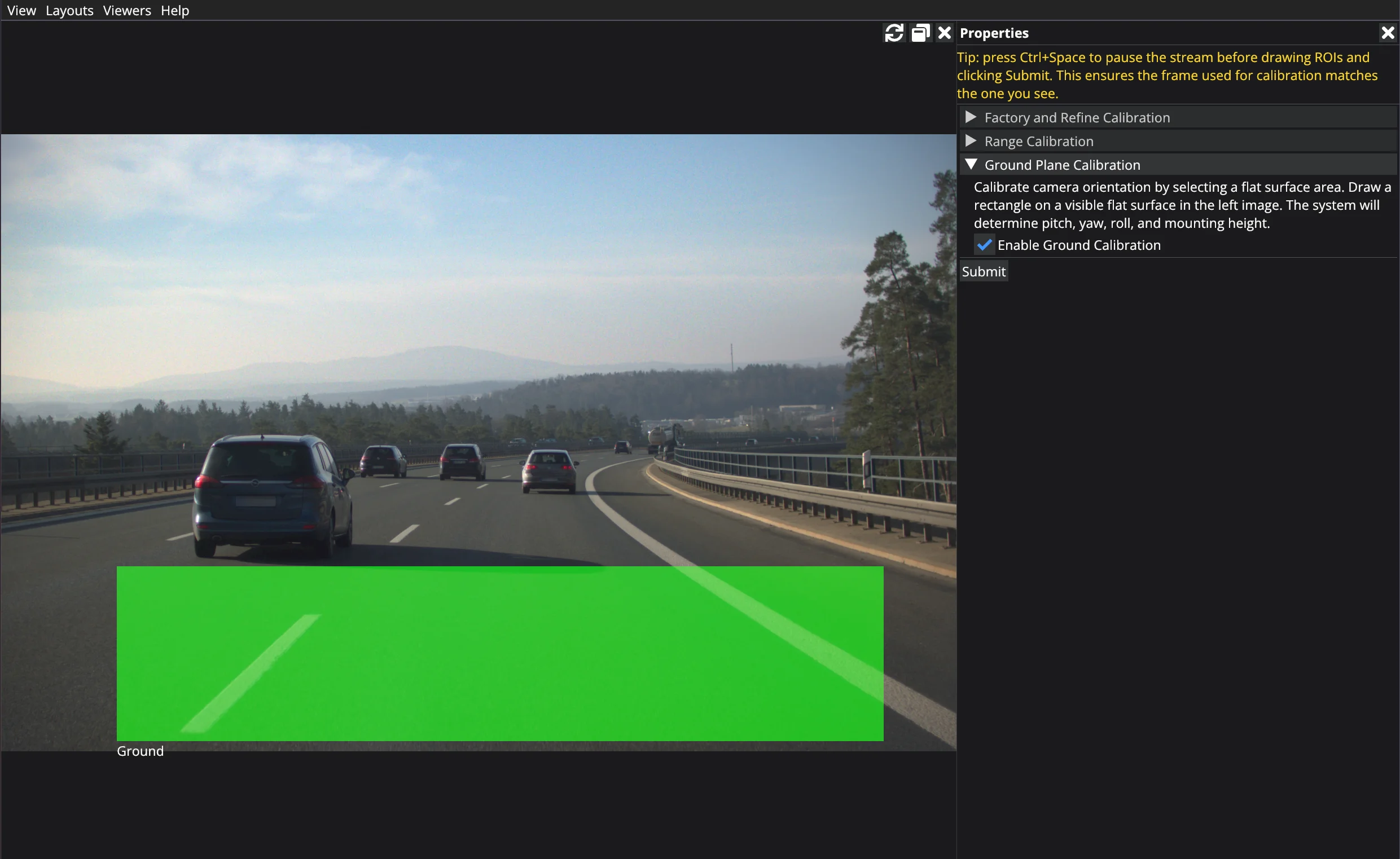
Ground Calibration
The Ground calibration option determines how the stereo sensor is oriented relative to the ground (see Stereo Sensor Coordinate Configuration). Run this whenever the sensor's mounting position or tilt changes.
Run Ground calibration only after Factory (or Refine) and Range calibration have completed successfully.
In the properties panel, expand the Ground Plane Calibration section and tick Enable Ground Calibration. Draw a rectangle directly on the left image over a flat patch of ground that is free of obstacles and markings, then click Submit.